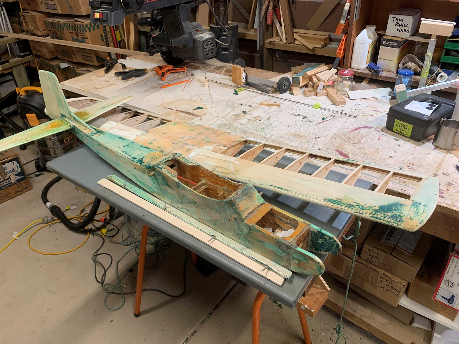
With my Freewing FA-18, I needed to attach the receiver to the top of the opening behind the access hatch, with the receiver upside down. This meant that I could not access the stabilization pots on the Lemon RX stabilized receiver that I am using. Because of this I used velcro to hold it in place so I can remove it to make adjustments, and then press it back in place.
One of our subscribers to our YouTube channel noted that velcro isn’t a good idea for attaching a stabilized receiver. That’s especially true when it is attache upside down – a heavy landing might knock it loose, with disasterous results if the stabilization is on.
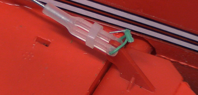
So, I’ve come up with an idea for using a tray to attach the servo to, with a tray holder fixed to the aircraft. Here is my sketch of the idea:
So, basically we are talking about using a thin piece of lightweight plywood for both the tray and the tray holder. Additional bits of plywood make the channels for the tray to be held in place. A stop at the end keeps it from being pushed in too far. For the seven channel receiver with servo connections positioned to the back, the cowl cover can keep it from going forward. However, even if there is no restraint in that direction, the cables will tend to hold it in place, and with it anyplace in the tray holder, stabilization will not be affected.
See the setup video here for how it is currently set up, and let me know if you have a better idea!
Want to know more about RC Jim? Here are some more details.
Typical of many young boys back in the 1950s and 60s, Jim got a start in flying model airplanes with a Cox 049 powered, plastic, control line plane. I think it might have been a P-40. That interest in planes was certainly fuelled by his Dad’s love of aviation. He had been a US Marine crew chief in WWII, island hopping through the pacific, patching together shot-up SBD Dauntless dive bombers.
By the way, every time they did a major repair, the pilot would require one of the mechanics to take a ride with him to check out the plane. This involved all kinds of high G aerobatic manoeuvres. My Dad was always one to raise his hand and go along for the ride!
Along the way, Jim did have a go at building some balsa models, including a SE5A biplane. The 35 McCoy in it had a go at slicing the end of his thumb nearly down to the bone. Strange, the way they locate the mixture control so close to the prop. Some years later, he had much more success flying a Ringmaster with an OS engine.
Growing up with an automotive engineer Dad, it’s no surprise that Jim pursued a similar career. Of course, as a teenager, he also contemplated a career as a race car driver, but that was a bit farfetched. None the less, at the completion of his engineering degree, Jim was working at the General Motors Proving Ground, with the freedom to drive his test cars around on some pretty nice test tracks.
While Jim loved his job, God had some other things in mind for him. During his time at General Motors Institute, he sensed a call into full time Christian ministry. So, following his marriage to his ‘perfect girl’ around the time of his graduation, the two of them moved from Michigan to Tennessee to get their training in ministry and theology. There Jim received his master’s degree.
Their involvement in ministry brought them to Melbourne, Australia where they led the establishment of what would become Living Springs Baptist Church. It was a multi-cultural church, with families from all over the world.
During that time, Jim’s two sons were approaching their teenage years, and the love for aviation was being passed on to them. With Dad’s encouragement they started flying the control line planes, and eventually got into radio control with a Great Planes Trainer 40 and a HiTec radio.
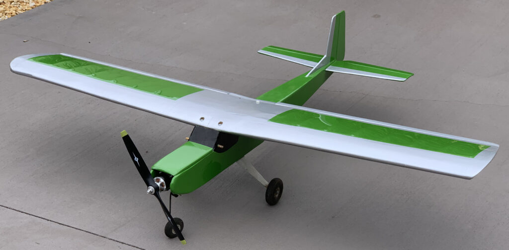
Being self-taught, it’s understandable that this plane was smashed multiple times. The first one was full throttle into the trunk of a tree, with the motor continuing flight into a nearby creek. We never did find that! The plane was rebuilt, re-powered with an OS Max 46 FX, and continued to be abused by the trainee pilots. On one occasion the wing was broken in half, and another time, that happened to the fuselage. That plane has been restored by Jim, and is still flying today (Click here for video).
As they progressed in their abilities, Jim and his boys acquired a Duraplane. It was also powered with OS Max, this one a 46 LA. It was fully aerobatic, and was designed to be highly resistant to damage, having a high density foam wing with a moulded in aluminium spar, a PVC square pipe fuselage in the front with an extruded aluminium section going back to a balsa tailplane.
They continued their philosophy of continuing to fly on a particular day until nothing would fly anymore, followed by a week or so of repairs!
Through this time, Jim and the boys were involved in the Australian Air League, and then moved into the Air Corps Cadets. As that group also involved girls, Jim’s older daughter also was a part of that. She ended up going to the Australian Defence Force Academy, becoming an electrical engineer, and continues to serve today in the aerospace realm. The older of the two boys decided to pursue a career in aviation, and following a time flying KC135 tankers for the US Air Force, he became a commercial pilot, and is now a pilot with United Airlines.
Once that church was on its own feet with a reasonable size congregation and a building, Jim and his wife entered new roles being part time in ministry and supporting themselves with secular jobs. They ended up with Jim being a pastor in Toronto NSW leading up to his retirement.
Living at Lake Macquarie, and with his boys being mostly away from home, Jim focused on boating related activities, with the planes left hanging in the garage. That continued for twenty years or so.
As retirement was approaching, Jim had been involved with a sailing club, racing an Impulse sailing dinghy. That was happening on Sunday afternoons, and the church wanted him to move from being the assistant pastor to be the only pastor, as they searched for a replacement. Jim decided that his involvement in sailing would interfere with that, so he decided to give that up. At first, he thought that racing remote control sailboats would be a good hobby to replace that with, but when he saw that his RC sailboat came with a four channel transmitter, the penny dropped, and he thought: I can fly my planes with this! One thing led to another, and he never did race the RC sailboat, but instead went head over heels in getting back into RC flying.
Jim is now happily retired, busier than ever in working on his planes and producing videos to help others along in the hobby. Of course, with his Christian background, reaching out to lift up others is a natural. Jesus Christ came to earth to do that for each of us. As we accept His simple gift of new and eternal life, it’s only natural that we would want to reach out to others. The most important part of that has to do with one’s eternal destiny, but it’s also consistent to help others in practical ways regarding everyday life, and even our hobbies!
Lemon RX continues to impress us with the development of their excellent receivers. Having a low-cost alternative to Spektrum®, while still being compatible to DSMX® has been great. And Lemon RX have always impressed us with their reliability and excellent stabilization. Over the years they have been working at making their setup and programming easier, and I have now gotten used to selecting the flashing lights during setup and find that quite easy. But now they have gone a step further with their Gen 2 receivers, allowing you to do most of the programming through your transmitter. And the transmitter can be one from Spektrum® or even one with Edge TX, such as Radiomaster.
So, are you excited to find out how to do it? Here are the simple steps:
Update the firmware on your transmitter, if it’s not current.
Bind your transmitter to the new Lemon RX Gen 2 receiver.
Power on the transmitter.
Navigate to the “bind” menu on your transmitter, but don’t press the button yet.
Power on the receiver.
Hold the “B” button on the receiver until it starts flashing rapidly, then let go.
Execute the “bind” on the receiver.
Check to see that your four basic channels (aileron, elevator, throttle and rudder) all go to -100/100 when you move the stick all the way in each direction. If not, return the gains to 100%. That can be on a single mode that you have selected.
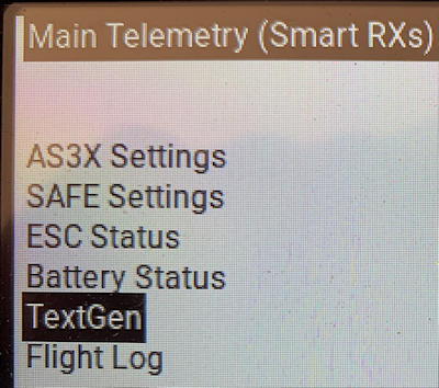
For a Spektrum® DX or NX radio, go to “Function List” and select “Telemetry.” Scroll down to an “Empty” item, and select it. Scroll through that down quite a ways to “Text Gen” and select it. When you have done that, make sure it is “Act” (Active) not “Inh.” Go back to your main screen, and with the receiver powered up, scroll to the right until you come to the “Lemon RX” telemetry page.
If you have a transmitter running Edge TX, press the “SYS” button, select “Tools,” then select “DSM Smart RX Telemetry.” In that screen, then select “TextGen.” With either of those, it should then show you the current settings for the receiver.
5. Unplug the power from the receiver, then plug it back in again.
6. Within 60 seconds, pull your transmitter control sticks all the way down and to the outside.
Hold them there until the display changes to show this:
7. Note that with any of these stick movements, the programming is looking for something very close to +100 or -100. Most transmitter control sticks will go below or above that when pressed all the way to the limit, depending on how hard you push on it. If it’s not working for you, get into a transmitter display that shows you the % value for each of the sticks, and see what you need to do to hit +/- 100.
8. The first line in the body of the text will have a number in front of it. That’s the menu item that you can change on that screen. The lines below it displays the status of all the items, not just the one you can change.
9. To edit the item, press the elevator stick down. I’m assuming you are in mode 2. As you look down to that item, you will see it has toggled between the value choices. Press down again, and it will change back. With your stick movements in the menu, all it takes is a movement of the stick to the limit, then right back. Sometimes it then takes a second or two for the action to show on the screen.
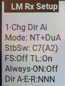
10. To move to the next item in the menu, move the aileron stick all the way to the right or left. Here is a list of the menu items:
1-Chg Dir Ai (Change direction of aileron response in stabilization. Note with this and the two items below, the three controls are listed first, “A-E-R” = Aileron, Elevator and Rudder, then the three settings follow in order: “N” is normal, “R” is reversed)
2-Chg Dir El (Change direction of elevator response in stabilization)
3-Chg Dir Ru (Change direction of rudder response in stabilization)
4-Chg Dual Ai (Single or dual aileron channels – the “Mode” is displayed first, “NT” or normal tail being the default. It then adds “DuA,” dual ailerons if you have selected that – see item 8 below)
5-Show Config (Show the configuration menu, and make menu items 8 to 15 able to display and be edited. Move elevator stick all the way up or down to select.)
6-Exit & Save (Press down to exit the menu and save your settings)
7-Ex & No Save (Press down to exit without saving the changes you have made)
8-Chg Mode (Change mode: DT – Dual servos for elevator VT – V tail RxOnly – no stabilization, just operate as a normal receiver NT – Normal tail, single channel for elevator, single channel for rudder.)
9-Chg Stb Sw (Change the switch used to turn stabilization on or off)
10-Chg Alys On (Used when you don’t have enough channels to turn stabilization on or off)
11-Chg TL (Turn throttle low “TL” on or off. With it “on,” if the receiver goes into failsafe mode, it will send a low throttle signal (-100) for less than a second, then stop sending any signal. This is needed for some ESCs which will keep the throttle going for a while after loss of signal from the receiver. It may or may not be appropriate for a some situations. See John’s comment below for further detail. Note that he refers to it as “throttle lock.”
12-Cancel FS (Return failsafe “FS” to default value. See the videos at the bottom of this article for instructions on how to set the failsafe to user selected values.)
13-Rs Rx (Reset all receiver settings to factory default values)
14-Cal V (Calibrate voltage “V” displayed via telemetry)
15-Cal I (Calibrate current “I” displayed via telemetry)
Sys Info (Date of system firmware in receiver)
There is an additional item that displays when you are not editing the items: “M Gain %.” It’s the level of gain that you have set on channel 8. You should have that assigned to a dial on your transmitter. It acts as a multiplier to the settings on the receiver pots. -100 will nearly turn it off. 0 (middle position of knob) will not alter the gain set on the pots. +100 will nearly double it. Turning the dial left or right will reduce or increase that value. The “nearly” that I refer to is due to the fact that the radio is capable of sending signals beyond the -100, +100 range.
That should give you all that you need. Keep in mind that you can still do the basic setup routine using the lights on the receiver, but using your transmitter gives you both greater control as well as a clear picture of what all the settings are.
Note that if you want to set Fail Safe to custom settings, you still do that using the “F” button on the receiver.
As always, happy flying!
RC Jim
Other related YouTube videos that you may find helpful:
Download a pdf of the article suitable for printing:
Permission is granted for individuals and clubs to print and use this information for their own non-profit purposes. Should any damages result from using this information, no responsibility is accepted by James Massey or RC Jim. Make sure that everything is safe, and test everything before flying.
RC Jim has received sample receivers from Lemon RX for testing and review, but that all began with Jim purchasing one and realising that it was a great product at a great price.
My son visited recently. We learned how to fly radio controlled models together over 25 years ago. After leaving home he didn’t fly them again until this visit. Having a couple of flights, he did a beautiful job. That doesn’t surprise me, as he is currently a commercial airline pilot, and previously flew KC-135 tankers as well as UAVs.
As he has been watching the RC Jim videos, he has heard me talk about various incidents – mine and others. He said to me: “Dad, you guys are much too casual about risk.” (or something to that effect) For some reason he thinks that crashing ought not to be part of flying! Imagine that!
Well, that did get me thinking about giving more attention to risk management. We do that in business – whether it has to do with a product that we manufacture, or just the operation of the business itself. And with that attention we then put in elements to protect it and us.
So, in the videos that I’m producing related to this article, I want to go through an evaluation of risk management regarding our flying, determine the risks, work out how to avoid and/or manage them, then make some recommendations related to that.
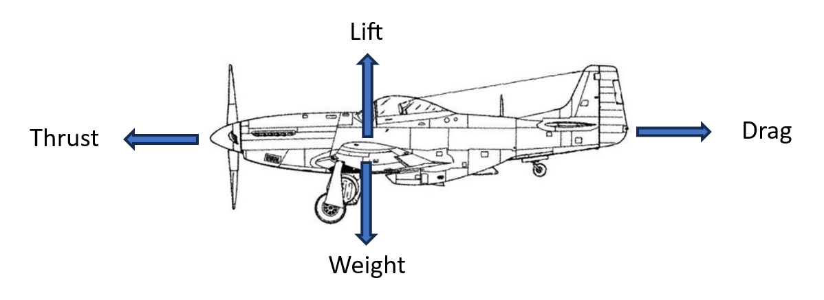
Failure Modes
We need to begin by considering what can go wrong, and how that happens. Those are called “failure modes.” In this article we are going to focus on the ‘disastrous’ sort, having to do with loss of control of the airplane when flying, resulting in a crash – potentially damaging people or property, including the plane itself. There are other important ones, such as shop safety when working on the plane, and especially not allowing the prop to chop your hands to bits in the pits, but we will leave that for another time.
Mechanical/structural
Failure mode
Mitigation (how to avoid or fix)
Over stressing the plane in maneuvers resulting in breaking a component.
– Proper construction – Evaluate the plane’s strength and fly accordingly Note RC Jim’s comments about the FMS Corsair wing with retracts compromising the structure. Click here for video.
Components vibrating loose – Control horns, servo arms – Wing attachments – Motor mounts – Control surface hinges
– Utilize thread locker where appropriate – Use pins to secure hinges – Inspect regularly – visually and by pushing, pulling etc. – Vibration isolators in motor mounts for glow fuel engines – Properly balanced prop How about control horns fastened to the rods with grocery store food bag ties! That’s how this model was when I acquired it!
Component missing – Failure to put in a screw or attach a clip – Failure to install the spar tube in the main wing – Failure to change out the spent battery with a fresh one
– Have a checklist of items to do before a flight, including a list of items to put in place – Always check the battery voltage before buttoning up the plane
Component shifting during flight – Battery slides forward or back – Battery pops off magnetic cockpit cover with negative Gs – Electronic gear flops around causing a connection to be severed – Antenna pulls itself into a coil and becomes less effective
– Have adequate provisions for securing battery – Don’t depend on a magnet to secure the battery – Secure receiver and ESC with velcro – Use a receiver with two antennas, and secure them with tape or a plastic tube so that they are right angles to each other – or use a receiver with built in antennas See “Great Planes Trainer 40 Antenna Placement”
Stripped gear in servo
– When installing servos, ensure that the control rod & surface do not hit a hard stop before the servo has moved the maximum. If it is going to do that, use a hole closer in on the servo control arm. – Make sure your servos are properly sized for the application. – Check at home and at the field that the servo is not forced to stop before it reaches maximum travel. – Watch the control surface as you slowly move the stick, and listen for a hum when it reaches its maximum position. – When testing the controls before flight, look for any “dead spots” as you move the control stick, and listen for grinding sounds. – Be careful when setting up mixing for flaperons or elevons where additional travel may be called for with a combination of control inputs.
– Tape cable connections. – When setting up, test servos with receiver while wiggling cables. – Regular visual inspection. – When handling cables, press together/press in all connections when you finish, making sure they are all fully connected. Note that over time, connectors handling high current levels will deteriorate. That can be evidenced by poor performance. Replace them when that appears to be the case.
Heat damage to motor, ESC, cables or battery – “Cooked” ESC damages BEC (battery elimination circuit), totally cutting off power to the receiver. – ESC fail safe doesn’t work, motor quits, plane crashes and possibly burns. – Overheated component causes the plane to catch on fire. – Electrical short in component causes “runaway” current through battery, resulting in fire or explosion.
– Make sure you have properly matched components regarding current capacity. – If your ESC has a mode in which it is trying to maintain a given RPM with each throttle setting, turn that off. That setting is only for helicopters. In a plane it can cause a huge current draw if the prop hits the ground. – When setting up your plane, make sure there is adequate ventilation to the motor, ESC and battery. – For large, expensive planes, you may want to use a separate battery for the receiver. If that is going to create a weight problem, you might consider using an ESC including a BEC which is physically separated from the main part of the ESC. – After each flight, feel each of the components (taking care not to burn yourself!) to see if any are getting excessively hot. Smell for any burning electronics. – If your battery is swelling, replace it and dispose of it properly. See our video re. That. – If there is visible physical damage to a component after a crash or other incident, replace it. See related YouTube videos: Electric RC Plane Component Selection Electric RC Plane Motor Testing All You Need to Know About RC Plane Batteries Introduction to ESC Programming for RC Planes
Low receiver voltage, causing motor to stop, and potentially loss of control. – Temporary voltage reduction due to high current draw. – Ongoing voltage reduction due to overdrawing battery.
See our relevant videos on ESC programming (above), and the video on fail safe settings for the receiver, set through the transmitter.
Loss of radio signal to plane. – Too far away – Antenna on plane or transmitter pointed directly at the other one. – InterferenceSpent battery in transmitter – Poor connection on transmitter battery
– A typical airplane transmitter has something over a 1 km range. Stay well within that. – Be careful around high tension power lines. – Make sure your receiver has two antennas which are positioned perpendicular to each other. – Where your transmitter has a bendable main antenna, set it to be roughly perpendicular to the line of sight between you and the airplane. – Use a transmitter that has two antennas, and a good frequency hopping protocol. – As you fly, rotate your body & transmitter to always be facing your plane. – Make sure the fail safe provisions of your receiver have been properly programmed. See our next video regarding the details for this. See “Great Planes Trainer 40 Antenna Placement”
Aerodynamic
Under powered, making it difficult to establish adequate airspeed.
– Try to have the maximum thrust equal to the weight of the plane including battery/fuel. For 3D aerobatics, it needs to be significantly more. – If slightly underpowered, allow a lot more runway length for taking off. Also use energy conserving techniques in flying such planes, such as diving to build up airspeed before doing a loop. See our YouTube video:Electric RC Plane Motor Testing
Improper balance
– Adjust battery position and/or ballast weights to balance the plane near the middle of the range recommended by the manufacturer. – Where that position is not known, start with 25% to 33% back from the leading edge at the distance out from the fuselage where the center of the geometric area of the wing is located. See our video on the details of how to do this: RC Plane CG Location & Balance. – If the side to side balance is way off of the centreline, add weight to correct – generally this is not a problem unless you have a camera mounted on one wing.For glow fuel planes, try to have the fuel tank close to the fore-aft location of the desired centre of gravity. This keeps it from changing the balance significantly as fuel is consumed.
High wing loading leading to a high speed stall
– Light wing loadings tend to help the plane handle sudden changes in pitch. – Planes with high wing loading (a relatively heavy plane for the size of its wings) need to be flown smoothly, without sudden control movements, especially with the elevator. You need to anticipate what you want to happen next, and move into it with gentle control movements. – Naturally, using light weight building techniques will help. If you are getting started, begin with a “foamy.” A good example: FMS Ranger 1800 RC Trainer Demo
Improper trim settings, making the plane difficult to control
When you first fly the plane, start with just flying the pattern, making trim settings down each of the downwind and upwind legs.
Personal
Pilot error – Brain glitch – Improper technique – Failure to take in relevant information – Evidence of a control problem – Airspeed – Proximity to hazards – Entering into a situation that requires a greater skill level than where you are presently at – Distraction or stress – Not performing remedial steps as a problem becomes apparent – Risky actions
– Get yourself in a good mental state before you fly. Interact socially with the other pilots. – Work on your flying techniques. Start with the basics, and get them really solid before moving into more complex things. See our video on Learning to Fly RC Planes. – Know your plane well. Fly at different airspeeds, and see how that affects the controls. Get several mistakes high, and slow the plane down to close to a stall and note the attitude of the plane and how the controls are responding. – If a problem becomes apparent: – Make sure you and the transmitter are facing the plane – Call out verbally to the other pilots and let them know what’s happening – If you have a battery fail safe programmed, reduce power and flick the switch to reset itIf the plane is not responding to aileron control, try the rudder – If the plane is headed for a crash, cut the throttle – Land as soon as possible, even if it means landing in the wrong direction. Again, let the others know what you are doing.
Other pilot failure
It’s always wrong to smash into another plane, even if they are doing the wrong thing.If another pilot is doing something unsafe, talk to them about it. Refer it to your club management if it continues to be a problem.
That’s what I’ve come up with thus far. If you can think of additional ones, put them in the comments under this YouTube video. Do the same with your additional insights on how to handle the above situations.
In our next video on Fail Safe Management, we will be looking at what you can do with the various electronic components. The ESC and receiver each have aspects of fail safe provisions that can be programmed into them. And the transmitter will normally be used to make the fail safe settings on the receiver.
Following that we will do a series of videos on how to make those settings on specific brands and models of radio gear. So, have a look at YouTube.com/@RCJim and subscribe so that you don’t miss anything!
How to select an electric motor power combination to replace a glow fuel engine in a radio controlled model plane.
Information needed
Given that you are re-powering an existing plane, it’s important to make sure that you get a new power setup that is right for that particular aircraft. So, begin by taking note of the following information:
Anticipated weight of the completed aircraft with battery. Take out the old engine and fuel tank and weigh the plane. For a typical ’40 size’ plane, add 550 grams (1.2 pounds) for the electric motor, a 4s battery and an ESC. That will get you started.
Space available for the battery. A 4s battery should easily fit in an area suited to a 12 ounce fuel tank – just about as long, and a bit skinnier. The skinnier part is good, because you may need to place the ESC adjacent to or under the battery. Going to a 5S will mean a slightly longer battery – so check before you buy!
What is the maximum prop diameter that can be used? Certainly, what you had on it before should be fine. Many electric motors like larger props, and they are more efficient, so consider whether or not there is enough ground clearance to go up a notch on prop size. For a ’40 size’ plane, about 50 mm (2 inches) clearance between the prop and the ground should be fine. For a tail dragger, make sure to position the plane in a level flying attitude while measuring. With tricycle gear you may get by with a little bit less if the nose gear isn’t too flimsy. How flat the ground is on your field, and how long the grass is will also make a difference.
What type of flying do you plan to do? Most often, it will be “sport” flying. That includes doing basic aerobatic manoeuvres, such as loops and rolls, but not sustained knife edge flying or hovering. Those would be considered “3D” flying.
If you are considering getting “budget/generic brand” components, then your brand of receiver may come into play.
Basics to Understand
Electric motors have a variety of numbers that describe them. First of all, the typical four digit number will give you the diameter and length of the motor in mm. The diameter may be either the case diameter or the rotor diameter, and similarly, there can be different parts of the motor that are referred to in the length. But, the first two digits are the diameter, and the second two are the length, and bigger ones give you more “oomph.” The other main thing you will generally find in the model number is the “kv”. That’s not kilo-volts, nor is it the amount of power delivered. It’s how many RPM are developed by each volt of electricity supplied to the motor. Keep in mind, that if you are going to use a 12 inch prop, you are going to need to spin it fast to get the thrust that you need, and that will mean a high kv number.
Related to the kv, as you go up in the number of cells in your battery (the “S” number), the voltage is going up, giving you more RPM. But it also means more weight! A 6S battery is quite a chunk, so if you are going for an easy to fly 40 size plane, you might want to stick to four or five cells.
There are other important factors that are helpful to know, so if you are new to brushless DC motors in aircraft, I would recommend that you watch our video: “All About Electric RC Planes.”
Selecting the motor
Right off the bat, things get a bit dicey. What we would like to do, is see a chart of motor data which includes thrust for various recommended props for each motor, go down the list, find the ones which have a thrust a bit more than the weight of a plane, then from among those, select one that can develop that thrust with a prop no larger than what our plane can handle.
With Cobra motors you can pretty much do that (Cobra website) – albeit, having to go through multiple charts. Also, they tend to be rather expensive, and are not necessarily better than other brands. And, I have found that each brand will have performance gaps. What you really want may be somewhere between the two nearest choices, and that difference may be a real issue. So, you may find that one brand has what you need, but not another brand.
So, as I look through the “sponsored” items with photos across the top of the search results, I see a Dualsky 40E tuning combination. That might work, but I want to replace a 46, so I see there is also a 50E, so I have a look at that. Following the link I go to that hobby shop’s listing, and see that they have the spec sheet for the motor there. It’s a Dualsky 4120C-V2 and it’s available with 560 to 350 kv. At the bottom of the sheet, I see that it is supposed to be suitable to replace a 46 to 50 two stroke engine, so that’s it! Or is it? Going up a row I see it needs a prop that’s at least 13 inch diameter, and generally with props you want to have the flexibility to move to different sizes, and with this there may be no wiggle room.
By the way, when you look at the manufacturer’s spec sheet, it will show you all the variations that are available for that motor, but the tuning combo will just be for one of them. You need to look at that one in particular.
Backing off, I figure that it might be worth considering the 40E. After looking at a couple of links I find the manufacturer’s spec sheet. The tuning combo uses the 820 kv motor, but it is available with 1020 to 519 kv. I note that the higher kv motors work with smaller props (13x8E to 15x6E for the 820 kv motor) , and the larger kv motors require larger props, but pull more watts. Watts are like horsepower. 1 HP = 746 Watts. I happen to also know that OS says that their OS Max 46 develops 1.65 HP, and I believe that the Watt ratings for electric motors are input power, not power delivered. So, it would seem that I ought to be targeting something well over 1200 Watts. However, given that they say this motor is equivalent to anything from a 32 to a 40, the OS 32 is claimed to have 1.12 HP. That’s 830 Watts. The spec chart says that the 820 kv motor draws 1040 Watts. So, that may be better than a 32, but it’s well short of the 46.
Next, I do another search and discover the Eflite Power 46, 670 kv. That is targeted specifically as a 46 replacement. It can be used with either a 4S or 5S battery, and with a 13x8E prop and 4S battery it pulls 670-745 Watts. It’s rated at up to 800 Watts, but the 5S battery might well pull it up over that with the 13 inch prop. But with the higher voltage, the prop would be spinning faster, and a smaller prop could be used. Unfortunately, we don’t have any data on that option.
I then begin to widen the search by looking at what each of my selected manufacturers have on offer beyond the tuning combos. Scanning through a list of their motors, Spektrum Avian 4260 800 kv looks like a viable option. 5-6S, recommended for up to 7.5 pound planes with sport flying or 5 pound planes for 3D, a 46 equivalent. 10×5 to 11×5 props. 1350 watts (burst). The higher kv allows the smaller props. This sounds more like what we are after. It would require a 60 amp ESC, and I’d probably start with the 5S battery, allowing something closer to my targeted 12 inch prop and keeping the weight down.
Looking at the Cobra motors, they have some good options for larger and smaller planes, but I struggled to find something that was a good fit for a 46 equivalent with a relatively small prop.
Testing the motor
Given that you are not using a complete combination of motor, ESC and prop provided by the manufacturer, it’s important to test what you have chosen to make sure the amps are within the manufacturer’s specifications. Spending all that money, you don’t want it going up in smoke on your first flight. So, when you buy the motor and other gear, also pick up a watt meter. Set up the plane on a bench, safely secured, and crank up the motor to full throttle, or until you hit the “burst” amps level. What the manufacturer specifies as the “burst” amps is typically what the motor can handle for about 15 seconds without melting the windings. If the amps are too high, then you need to go to a smaller prop. If they are lower, then you can move to a larger diameter or higher pitch on the prop to get added thrust. If you want to really know what’s going on, purchase a luggage scale, and use it to measure the thrust. For sport flying that should be a little over the weight of the plane, including battery. For details on how to do this, see our video: “Electric RC Plane Motor Testing.”
Final checks
Before placing your order, check the following:
Are there a variety of recommended props that will suit the ground clearance requirements?
Check the dimensions on the battery(-ies) that you are going to order. Will one fit in the plane with room for an ESC?
Check that the Amp rating on the ESC is well above the maximum burst amps specified for the motor.
When you receive the items:
Install them all in the plane and check the balance point. Adjust battery/motor location and/or add ballast to bring the fore-aft balance within specifications, and side to side balance reasonably even.
Set up the plane to safely check the amps drawn, and run a test using a fully charged battery. Change props if necessary.
Feedback
I’ve written this article, and expect to do a related video, because of a question from one of our YouTube channel subscribers. It may be that your question will prompt something similar. My goal is to help you to enjoy your hobby even more by helping you to learn and grow in what you do. Some of you are well ahead of me, and you may be able to instruct me in certain areas, so whatever your situation might be, get in touch. You can use the contact form on the website, or respond to the specific video on YouTube. As always, happy flying!
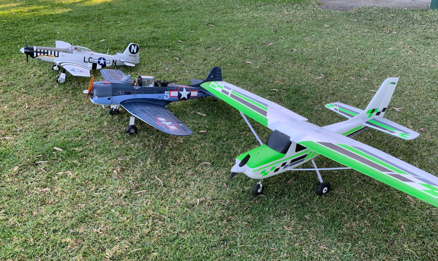
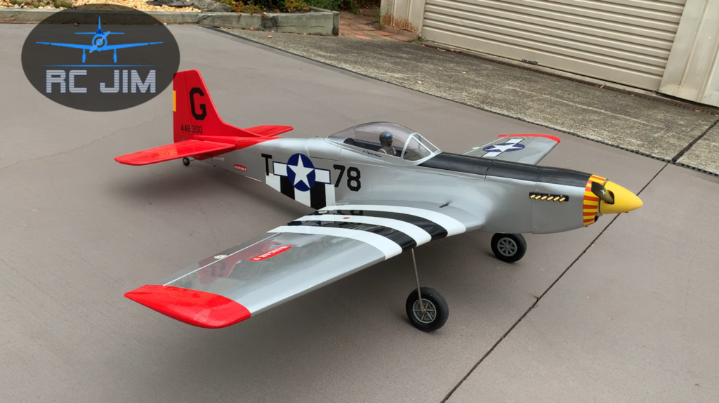
I happen to own two North American P-51 aircraft. Oh, I should mention that they are radio controlled models! None the less, they are exciting to fly, and I love to make low level passes with them and imagine what it would be like inside flying them. Unfortunately, on one rather windy day earlier this year I was flying my Hangar9 Red Tail P-51, and it was handling a bit weird. To make it worse, as I was coming in to land, as I came over the trees at the end of the runway, I hit some turbulence and the plane stalled. As P-51s love to do, it immediately dropped the nose. I hit the throttle, hoping to recover, but only managed to hit the ground at a great rate of knots!
The damage was pretty horrible, as you can see on my damage assessment video. A smashed fibreglass cowl, mangled front of the fuselage, plus nearly broken in half in the middle. I really liked that plane, so I decided to repair it. There were numerous issues along the way, but we eventually got it completed. Again, you can find a series of videos on our YouTube channel that walks you through each aspect of the repair.
In coming near the end, I got thinking that it would be good to be a little more true to the original. In particular, Hangar9 had put a white, Caucasian pilot in it. Apart from a few commanders in the early days of the Tuskegees, all of their pilots were African-Americans. Then I got searching for Dan Willoghby, the pilot named on the side of the plane, and I couldn’t find anything on him on the internet, and I even went through a list of the Tuskegee airmen, and couldn’t find him. Nor could I find anything on “Amazin’ Grace,” the name of the plane. It’s a name I love, but it was a bit of an issue.
So, I got looking for a worthy Tuskegee Airman pilot to have in my plane. I came up with General Charles McGee. He didn’t become a general until late in life, and it was an honorary title granted by the US Congress, but a worthy one.
Charles had a grandfather, who had been a slave. His dad did a number of things in life. He was a teacher, a church minister, and served as an infantry chaplain in World War I. Charles was at university studying engineering when Pearl Harbour was hit and America officially entered World War II. It was looking like he would be drafted, and having heard from his father what war was like on the ground, he wasn’t real keen on that. But he also heard of a bit of an experiment that the US Army was doing in training black men to be aviators and support personnel at Tuskegee. So, he signed up for that.
Entry criteria was really tough, but he made it in. A couple of days before being sworn in he married his wife, whom he stayed with until her death. Perhaps you are picking up on some things that I found really appealing about choosing him. A Christian, trained – at least partially – as an engineer, fighting against the culture of the day to do something that he really wanted, and finding the love of his life and sticking with her through thick and thin. That’s my kind of guy.
So, Chuck was sent to Italy and began flying missions in February 1944. During that year he flew 137 missions. I read somewhere that he is one of the few fighter pilots who shot down three enemy fighters in one day. I think they were Me109’s, from memory. Following his deployment to Italy he was returned to the States where he became an instructor for B-25 bomber pilots. I suppose that as he had protected so many of them, he could give the pilots some ideas on how to avoid getting shot down.
Speaking of that, the Tuskegee Airmen had an outstanding record for bringing home their bombers safe. Rather than chase after enemy fighters, they would engage them when they were threatening their bombers, but if they were hightailing it for home, they would let them go, and protect the bombers from others coming in after them. Out of 179 bomber escort missions, each of which would have had something like 100 bombers in it, they only lost 27 bombers. In 172 of their missions, they didn’t lose any.
Charles McGee went on to fly in two more wars: Korea and Vietnam, clocking up a total of 405 combat missions. He continued in the airforce in various command positions until retirement. In 2020, with support from the Air Force, the US Congress passed a bill to grant Charles McGee an honorary promotion to the rank of Brigadier General. He passed away in January 2022 at the age of 102.
But perhaps the most outstanding achievement in his life was his character. He has been described as a person who was humble, kind, and constantly encouraging others. When asked about it, he attributed that to his “lifetime devotion to Jesus Christ.” He wanted to be an example to young people in his family, his community and in his military service.https://en.wikipedia.org/wiki/Charles_McGee_(pilot)#Later_life_and_death
Or, are you and instructor who would like to have some help in training your students?
I’ve put together this training material to help with both of those matters. It’s still early days in developing this programme, so let me know how it can be improved. In the meantime, I expect that you will get a lot of benefit from it.
While the material is copyrighted, I grant permission for individuals and clubs to use it in their training when provided without cost.
As I read the Facebook post today of a 15 year old boy joining our club (Central Coast Model Aero Club), I was reminded of how I got started in seriously flying radio controlled model aircraft.
I inherited a love for aviation from my Dad, who was a crew chief in the US Marine Corps during WWII, island hopping through the Pacific, patching up Dauntless SBD dive bombers. I, in turn, flew control line planes as a boy, and dabbled a bit in flying full size aircraft as a young adult. When my own boys came along, we got started with control line planes, and when they got old enough, my boys both joined the Australian Air League, and then the Australian Air Force Cadets.
As they got into their teenage years, I decided to bite the bullet, and spend the money to get us into radio controlled flying. Back then the dollars weren’t all that much, but for us it was a lot. Our family didn’t have surplus finances, but I felt it was a good investment. So, I bought a kit for a Great Planes Trainer 40, an OS Max FX46, and a 4 channel HiTech radio, and we got started putting it together.
Initially, I didn’t even know that clubs existed for model aircraft enthusiasts, and our initial flight attempt was at a Christian Camp, which had some open areas. Not knowing much of anything about what we were doing, I put the plane down on the field, at the end of which was a creek and a stand of trees. Pushing the throttle all the way forward, the plane accelerated like a bat out of a cave, but for some reason it didn’t go up into the air much at all, striking the trees at full throttle a few feet off the ground.
Now, certainly, that couldn’t be pilot error, could it? And, as a former engineer, there couldn’t be anything wrong with the way I built it, set it up, and verified everything with numerous tests. 🙂 Oh well, obviously I missed a few things, and the result was that the plane was in multiple pieces, and we never did find the engine! It’s probably still there in the creek.
Well, I’m a great believer in restoring what is broken, and so I rebuilt the plane, and replaced the engine with a new one. It’s a bit like what God has done in my life, and in the lives of many others. Broken people that some would say are only destined for the rubbish bin. Ones that seem to have no value. Yet they are loved. Loved by God, and, believe it or not, loved by others down here. Loved so much, that Jesus Christ was willing to die for their brokenness. Way back, hundreds of years before He came to earth, the prophet Isaiah told us what Jesus would do:
“All we like sheep have gone astray, we have turned every one to his own way, and the Lord has laid on Him (Jesus) the iniquity (sins) of us all.”
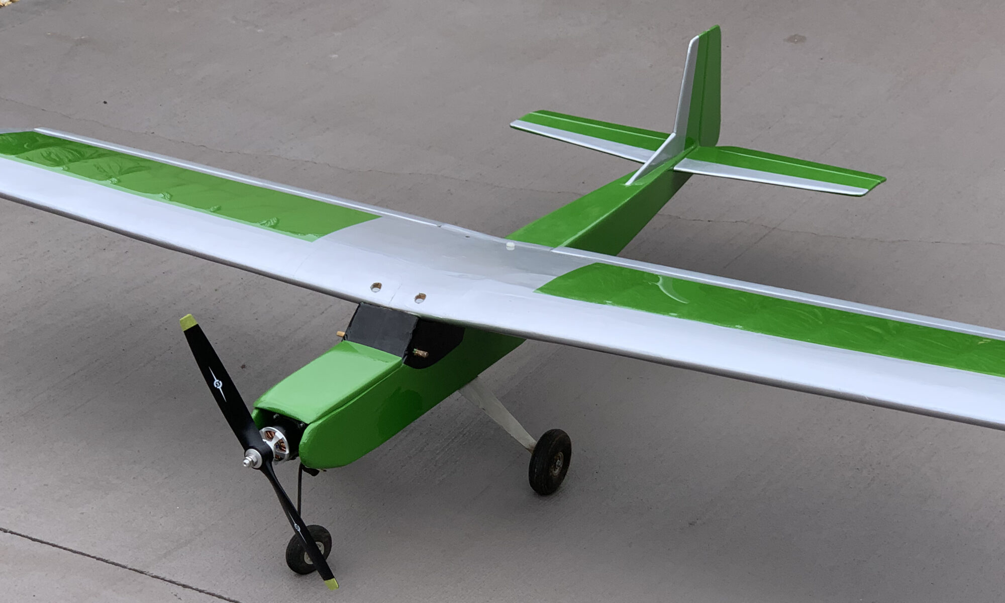
So, needing a new “engine” and broken parts restored to be like new, I believed in what Jesus did, and called on Him to be my Lord and Saviour and became a new person in Christ. Something that is available to everyone. Well, that was also my approach with the Great Planes Trainer 40. It doesn’t perfectly fit the picture of what God did in my life, but numerous times things would happen, and either my boys or I would crash the plane. By the way, after hanging in the garage for over 20 years, I finally restored it again – nearly ready to fly. Here it is:
Eventually we added another plane, a Duraplane, that was supposedly indestructible, with an OS Max LA46. But we managed to break it as well.
Eventually we joined a club, but it didn’t have the sort of support that we have at CCMAC, and most of the time we would be flying by ourselves at the field. We would fly the planes, do some dogfighting (not recommended!), and continue until nothing would fly anymore. Going home we would then repair everything, and then at the very next opportunity, get out there and do it again!
The boys grew up and went their separate ways, and my wife and I moved from Melbourne up to Lake Macquarie, north of Sydney. Being near the lake for many years I just focused on enjoying the water, but I kept my planes – what was left of them – hanging in the garage, as a reminder of the good ol’days.
Finally, nearing retirement, I decided to get out of competitive sailboat racing, and was looking for something else to focus on. Getting back into radio controlled flying was a natural, and boy, have I been enjoying it!
I’m continually adding aircraft to my hangar. Some of them are the old ones that I flew over 20 years ago. There’s about three of those in the repair/restore queue. Then, I just might help my son complete his big Citabra Decathalon that he never did finish building. And, one of these days I’m going to experiment building some planes out of foam board. So, keep on watching the YouTube videos, and see what’s happening next!
All you need to know for your electric RC aircraft�
We need to start with some basics about what the ESC is doing.
Click above to watch this content with explanations on YouTube
What is an ESC?
It’s an “Electronic Speed Control.” This device is powered by a battery and sends pulses of current to the motor based on the throttle signal sent to it from the plane’s receiver. Because it is powering a brushless DC motor (BLDC), it needs to send a type of three phase current to the motor. Those are pulses of electricity going through three separate wires, one after the other, and overlapping each other.
The timing of those pulses is based on the speed that the motor is actually turning. Every time a pole in the motor passes a magnet in the motor, a small pulse of electricity is generated that returns through the power wires. The ESC detects those, telling it the precise position of the rotor, so it knows when to send each pulse of electricity.
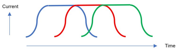
Partial throttle will break up each of the three pulses into a series of individual short bursts. The voltage being sent at the top of the pulse is still the full voltage that the battery can deliver, it’s just that it doesn’t need that for the full length of the pulse to deliver the amount of power needed for the partial throttle setting. That’s what controls motor speed. The percentage of time that the power is on is referred to as the duty cycle. So, full throttle is a 100% duty cycle, and 1/3 throttle is a 33% duty cycle.
For the sake of our discussion, we will refer to the full set of bars as shown above as the “pulse”, corresponding to the solid line in the diagram. The individual smaller bursts of electricity that make up the “pulse” will be referred to as “bars.”
Keep in mind that no burst of electricity is going to form a perfect rectangle, looking at current over a period of time. The reason why the main pulse ramps up on an angle is due to the fact that there is impedance or resistance to the flow, and it has to gradually accelerate to get going. Each of those rectangular bars will do the same thing – it’s just hard for me to draw it that way! In the corresponding video to this document, I do a better job of showing what is actually happening.
The number of bars per pulse is going to depend on the PWM (Pulse Width Modulation) frequency set in the ESC. A very high PWM frequency will give several bars per pulse at full RPM. However, the PWM frequency is often set to be just a tiny bit faster than what the pulses need to be at full throttle. So that might allow for two of them to fit into a pulse at half throttle. The problem comes when the rate of pulses that the motor needs is faster than the PWM frequency. That might cause a complete pulse to get missed, and that will cause the motor to be noisy and not run well.
Every time the ESC turns off the power at the end of one of those bars, heat is generated as the power flowing through the circuit needs to get dumped through an electronic component that has resistance. That both consumes power and creates heat. Because of that, the ESC is going to perform the best with the minimum rate for the PWM frequency. But, narrow, quick pulses will more closely approximate the desired curve that will make the motor perform the best.
So, there will be a trade-off between the two. Most flyers will simply accept the default PWM frequency, as long as the motor runs smoothly. In tests that I have seen, there’s only a 2% increase in power between the minimum and maximum frequencies. So, generally we stick to the low end of the range, as long as the motor runs smoothly, for the sake of the ESC. If it’s noisy, increase the frequency to see if that stops the noise.
Note that the PWM frequency will remain constant no matter what the motor RPM is. But the rate at which the pulses are delivered at low RPMs is much lower than what it is at full throttle. Because of that there are many more bars per pulse at low RPMs, helping the motor to run smoothly when slow. So, a characteristic of a motor with too low of a PWM frequency would be one that may run smoothly when slow, but at some higher RPM it gets noisy, and that gets worse the higher the throttle goes from there.
Another observation is that apart from the BEC (battery elimination circuit), which is used to power the receiver, the ESC is not a voltage regulator. Whatever voltage is coming in from the battery is going to get delivered to the motor. As the motor has a given “KV” value, RPM per volt, and the battery voltage is going to decrease during your flight, the full throttle RPM will be higher at the start of the flight than at the end. The ESC is just switching on and off that voltage to get the desired amount of power out of the motor. It reminds me of some WWI aircraft, such as the Sopwith Pup, which didn’t have a throttle, per se. They just switched the magneto on and off while landing, taxiing or other times that they wanted partial power!
What can be adjusted on an ESC?
Throttle range calibration
One thing that everyone needs to do when setting up a new ESC, even if it’s in a purchased BNF plane (Bind And Fly – ready to go, just add a receiver and a battery), is to calibrate the throttle. Sometimes, the way it comes from the factory, it’s not actually giving you full throttle when the stick is at 100%.
Brake
Your ESC has the capability to use the current generated from simply having the air spin the prop to be used to try to run the motor in reverse, acting as a brake. That’s really good in a car. It also may be beneficial if you have a glider with a folding prop. Furthermore, I’m told that it’s less likely that you will break a prop with a belly landing if the prop isn’t spinning. So, it might be a good idea to set the brake if you have a hand launch plane without landing gear. Apart from that, a free spinning prop is going to help a motor be more responsive to hitting the throttle after having it cut, such as in some aerobatic manoeuvres. The ESC is able to keep track of the motor position as long as it’s spinning. So, it’s immediately able to start the pulses where needed without delay. If the motor has stopped spinning, then the ESC needs to do a bit of investigation to work out which coils to fire before it can get going full on. One last factor is that a free spinning prop actually causes more drag than a fix prop that is not spinning. If you have a ‘dead stick’ situation far from the field, that might be good, but my experience is that generally is good to be able to slow down the plane coming in for a landing. We have trees on each end of our field, and if you don’t have flaps, it can be a challenge to get some planes stopped in time!
Note that some ESCs may refer to the brake as a “slow decay mode.” Also, some ESCs give you more than an on/off choice. You can have it slowly come to a stop.
Direction of Rotation
While you can always swap any two wires going from the ESC to the motor to reverse the direction of rotation, there is also an option in the ESC to do that. What you don’t want to do, is what I did during one very serious brain fade moment.
I brought a newly set-up plane to the field, thinking that I had gone through and verified everything several days earlier at home. In fact, I believe I had done that, but then afterwards, I must have opened things up to do something and reversed two of the leads going to the motor. At the field I went through all the control surface movements with the transmitter, did the range check, and all was good. But I didn’t run the motor on the bench. Thinking that all was ready to go, I carried the plane out to the flight line, checked the control surfaces again, then gave the motor a blip, and it pushed the plane backwards. I then thought, “I know how to reverse controls on the transmitter,” so I quickly got into the servo menu and reversed the throttle. With the stick down, it then gave me full throttle in reverse! Not a pleasant moment in front of all my mates at the club! Not to mention, dangerous as well! So, that was a great moment in developing my character. It will make a great chapter topic for a book one day: “Humility and How I Achieved It”! Just avoid those sorts of brain fades and we will all be happy!
PWM Frequency
Typically, there will be multiple choices that you can choose from. A typical range might be from 8 kHz to 32 kHz. If you want to calculate what value to use, the common formula is:
KV x Vnom x Poles divided by 20, where:
KV = the kv value of the motor (rpm per volt)
Vnom = nominal voltage of the battery (LiPo: 3.7 V x number of cells, if wired in series)
Poles = the number of magnetic poles in the motor (not coils)
This gives you the value in Hz. To get kHz, divide that by 1,000. You then select a PWM frequency that’s the next option higher than the value you calculate.
I might mention that the above calculation is what I have seen in several places on the internet, but there are still a few things that I’m trying to get my head around. Why use the nominal voltage, when the motor is going to spin faster when the battery is fully charged, requiring a higher frequency? Typically, I’m finishing a flight when I get down near the nominal voltage. I’m targeting 3.8V for that.
Secondly, the formula assumes that there will be three electrical cycles per magnetic pole for each rotation of the motor. But there are lots of poles, and lots of coils, some of them operating at the same time, and others at different times. It seems to me that may be a much more complex situation than the simple calculation above.
So, for the moment, figure that if the default setting works fine, leave it. If it gets noisy at high RPMs, increase it until it runs smoothly. Then for you guys who are like me, one day I’ll fully understand it, and produce a more in-depth video on what’s happening!
Slow Start
For geared or high load applications, a slow start is needed to avoid ripping apart the drivetrain or cooking the electronics. But, for most airplanes we want a quick response to the throttle. Most ESCs will at least have two choices, quick and slow. Some have another option in between those.
Heli/Governor Mode
Some ESCs can be used for helicopters. Naturally they will need the slow start mode. But there is also another option on some ESCs. What that does is to have the throttle select a target RPM. So, when you move the stick to a given position, it will do it’s best to keep the RPM constant at that level, no matter what the load is. Dial in more collective, and the ESC will add power as needed to keep the rotor spinning at the same speed. I was told that a YEP ESC that I cooked recently with a prop striking the ground at the beginning of a take-off run was likely due to it having come to me with it in that Heli mode. As the prop was digging into the ground at a high throttle setting, the ESC was doing its best to keep it spinning at a high RPM, and the 80 amp ESC went up in smoke!
Battery Type
Some ESCs will give you a choice, such as a nickel-based battery vs. automatic detection. The main thing that is doing is setting up what the minimum voltage should be, as that is a different percent of the maximum voltage for lithium batteries.
Timing
Don’t confuse this with PWM frequency. Timing is similar to ignition timing on a car engine. Firing the pulse a bit early is needed at high RPMs to give the current time enough to generate the necessary magnetic field when it is needed to pull or push a magnetic pole. Where you have the option of changing this, you will likely have a bunch of choices. But, most likely you will have an automatic option. Essentially, motors with high numbers of poles, such as large outrunners, need a higher number of degrees for the timing. However, it is rare to need to change this.
Low degrees of timing advance will tend to be more efficient, with the motor running cooler. Higher amounts of timing advance may be needed to achieve top RPM in some motors.
Other Options
Each manufacturer’s ESC will be a bit different from others. Some will have more options than others, and it’s not unusual to find it very confusing when you are reading the instructions as to exactly what some of the options are! So, along the way we will be producing some videos going through specific ESCs, how to program them with the throttle stick, how to do it with a programming card, and along the way, seeing what each option actually does. So, subscribe to YouTube.com/@RCJim and you will be able to work out what it’s all about!