

This article is intended to orient new users of Radiomaster radios to how they function. You may already be familiar with another brand or type of radio, or Radiomaster could be your very first. Either way, this information should get you going!
While our focus will be on their flagship product, the TX16s transmitter, you will find that it operates in basically the same way as their other, more basic transmitters.
Basic characteristics
The transmitter has two distinct functions, each operated by their own firmware (software).
- The computing function. This takes inputs from the sticks, switches and dials and works out what the output level should be for each channel, based on parameters that you have supplied. Those would include rates, levels of expo, mixing, flight modes and a host of other things. A variety of open-source firmware is available to do this, but most of their radios are shipped with EdgeTX. The same hardware is used for this regardless of which system you decide to use.
- The transmitting function. This is hardware related, and each type of hardware will have its own firmware. The hardware can be what is inside the transmitter case, or a module plugged into the JR bay on the back of the case. Two are available as the internal module or as an added on external module.
- The multi-module, often referred to as a 4 in 1 module. The latter is referring to the fact that it has four different computer chips inside for the basic function, and most computer manufacturers will use one of those four chips in their own transmitter. So, it’s then just a matter of Radiomaster working out what to have in their firmware to make it function with the same output as a given manufacturer. They have done that for dozens of different protocols that you can choose from. That allows you to use your Radiomaster transmitter to control a plane which has the other manufacturer’s receiver in it with its own unique protocol.
- An Express LRS module. It is a long-range system commonly used by drone flyers with a potential range in excess of 20 km. It can also be used by line-of-sight pilots. Note that the external ELRS module has greater potential transmission power and range than the internal one. That is because it has a cooling fan.
Thinking of transmission power, either module is available as either FCC or LBT compliant. LBT is for radios used in Europe, and their power is limited to less than what the FCC allows. FCC is used pretty well everywhere else in the world.
Transmitter Case and Controls
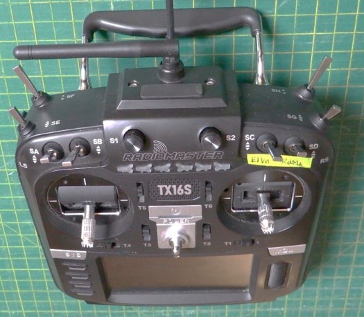
- Eight switches, labelled SA to SH. 2 x two position, one of those being momentary. 6 x three position.
- Two dials, S1 & S2. They both have a detent that you can feel at the halfway point.
- Two sliders along the side of the radio, LS & RS, easily operated with your ‘pointer’ fingers while your thumbs are on the sticks. They also have a detent at the halfway point.
- Six buttons just below the dials, labelled 1 to 6.
- Six trim tabs, T1 to T6.
- Two joysticks. They can be setup in different modes. Mode 1 is common with a lot of older flyers, but mode 2 is more popular. With it the right hand joystick is like a normal airplane joystick, controlling ailerons and elevator, while the left hand stick does the throttle and rudder. Unlike some other transmitters, the joystick length is not adjustable, but the stick end is removable and could be replaced with something different. The gimbals utilise Hall Effect. That means that they don’t have potentiometers with rubbing parts that can wear out. The only wear on these gimbals would be bearings. And, if that is a concern, you can pay a fair bit extra and get precision machined AG01 gimbals. Those could also be added later.
- A power button. Hold it down until the light either goes on or off to toggle the power.
- A colour touchscreen. It has a header strip across the top, the ability to show trim positions along the side, and a main part of the screen for primary content. Each area, as well as the background can be customized, showing the content you select.
- Two main menu buttons, SYS and MDL. The SYS, or System, button gives you a menu of items that cover things that are the same for all of your planes. The MDL, or Model, button has a menu for items that you configure for each individual airplane. Pressing either button brings up a series of tabs across the top of the screen. The content of the main part of the screen will be the items that can be selected or modified for each one.
- Four menu buttons to the left of the screen: RTN – return, Page > – move to the next tab to the right, Page < – move to the next tab to the left, and Tele – a shortcut to take you to Screens Settings under the Model menu. The page buttons will also move you across to different screens that you set up.
- A scroll wheel to the right of the screen. Scroll to move through menus, push in to click and select items.
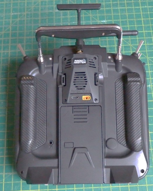
- A USB C socket on the top to connect to a computer. Next to it, a mini-plug socket to connect with a cable to another transmitter for a wired buddybox.
- A USB C socket on the bottom to charge the battery.
- There are a variety of options for the battery, but Radiomaster has a 7.4V 5000 mAh Li-ION battery that they recommend and can provide.
- A Micro JR bay on the back. An external transmitter or receiver can be attached there.
- The transmitter is provided with an alternate set of finger grips for the back, a USB-C to USB-A cable and a spare set of gimbal springs. Note that a USB-C to USB-C cable has been reported not to work for the computer connection, and the USB-C to USB-A cable needs to be data capable. Many of them are just designed for charging a device.
- A carry handle at the top and lanyard eyelet on the front are provided. I have noticed that my lanyard has been scratching the screen. This would be happening when I have the lanyard attached to the transmitter, but not around my neck. As it slides back and lanyard around your neck at the field, and just clip it on to the transmitter when you are going to fly.
Setting Up Your First Model
We will assume you are going to use the Multi-Module, but most of this will also apply if you are going to use ELRS. Should that be the case, you will find our video on Setting up Express LRS very helpful to supplement what you learn here.
Power up your transmitter. First, we want to show you how the MDL button is used. A quick click will give you the Model Menu. Holding it down for about a second will give you the Manage Models screen. That’s what we want for now.
Select “New” in the upper right corner. Select “New Model.” For now, select “Blank Model.” There are a variety of wizards and templates available, but once you have your first plane set up, we will be using an existing model as a template. Furthermore, you need to understand what the menu items do, so going through the full process will help you better understand what’s going on. So, prepare yourself for a rather lengthy process on this first one, but it will be quite easy for each one after that!
Opening screen
For a start, click the TELE button. That will then show you how the screen is laid out. We will not go into the details now, but just make sure that all the items from “Top bar” down to “Trims” are ticked – lit up with yellow, and the blue dot to the right. Now click the RTN button, and let’s have a look at the screen.
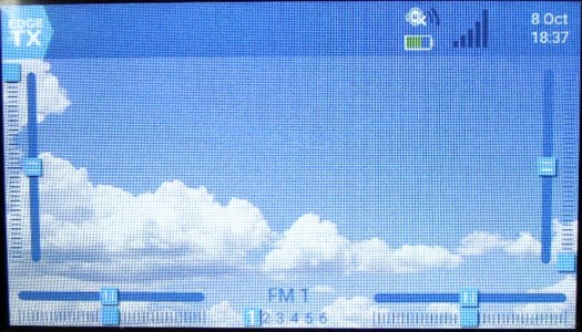
- The background will be the EdgeTX graphic. This can be changed. I use a picture of the sky with some puffy clouds.
- In the top left corner, there will be an EdgeTX button. When you click it, it will give you a menu of shortcuts and other items. Most likely you will only use the “Manage Models” item here.
- Along the two sides and the bottoms you will see bars with square markers to indicate the position. Far left and far right show you the position of the sliders. At the very bottom you see two bars that show the position of the dials. And, in the middle of the bottom, it shows you which one of the six buttons up near the top are pressed.
- In the header bar across the top, on the far right you will have the date and time. Then next to that is radio information. The lines coming out from the speaker show you the speaker volume. The battery below that shows you the charge level of the transmitter battery. And the series of bars at the right show the signal strength.
Model Menu
So, let’s go to the Model Menu now. Give the MDL button a quick click.
In the far top left corner there is an icon of a circle around a plane. That will take you back to your main screen for the plane.
The rest of the items across the top are tabs for various screens. We will start with the first, Model Setup. Touch on the box (or scroll and click with the scroll wheel). You can now use the displayed keyboard to replace the Model name with what you want. “Labels” is used to put your planes into categories. For now that’s either “Unlabled” or “Favourites.”
Clicking on the Model Image box will allow you to select a graphic of an aircraft to display on the main screen. Unfortunately, many of the ones that come with your radio are not described very well with the file name. But, pick something. You can change it later.
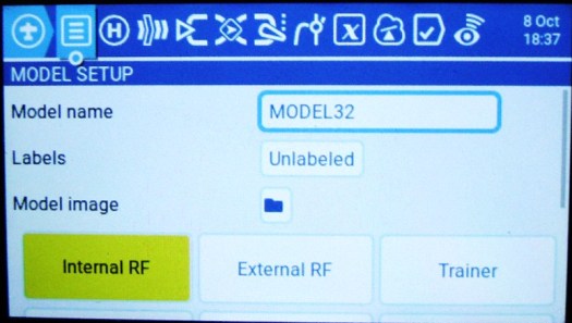
Now, click the “Internal RF” box. That’s for settings on your internal transmitter module. For Mode, select “Multi.” On the screen that comes up, touch the box to the right of “Multi” and select the one that’s appropriate for your receiver. So, if you have been using Spektrum receivers, select “DSM.” Note that anything with “RX” at the end is a receiver. Those are for buddybox setups, so just make sure you haven’t selected one!
For DSM you will note that next to Module Status it gives a version number, then “AETR.” That is indicating that in the transmitter, the channels will be setup in that order, with the throttle on channel 3. It will still send the signal to the receiver in the DSM order of TAER.
Under RF Protocol, options for the mode chosen will be displayed. For DSM you could select either “Auto” or the most recent, currently X2F. I do the latter in that I certainly do not want to be flying with DSM2.
Leave the other items as they are. Note that at the bottom of this page there is the “Bind” and “Range” buttons. We will use those later. Press RTN.
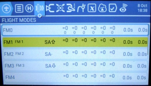
Press Page > twice to get to “Flight Modes.” We will set up three, to correspond to a three position switch. Touch “FM1.” Touch the “Name” box, and type in “FM 1.” Touch the ✓ in the bottom right corner. Touch the “Switch” box, and then move the three position switch down, and then back up to the position that you want for Flight Mode 1. Touch on the switch description that has been selected. I use “Switch A” in the up position, so it would be displayed as “SA” with an up arrow next to it. Press RTN.
Now do FM2 and FM3 in a similar way, but with the switch ending up in the appropriate position.
Now press Page > again to get to the “Inputs” page. This is where we will set up rates and expo for each flight mode.
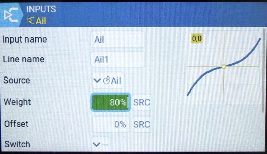
Touch on the long box next to “Ail.” Touch “Edit.” Touch the box next to “Line name” and type in “Ail 1.” Touch the box with the percentage figure next to “Weight.” You can adjust it up or down with the – or + buttons. Alternately, you could have scrolled to it with the scroll wheel, clicked the scroll wheel to select it, then use the scroll wheel to dial it up or down. For now, set it at 80%.
Scroll down to “Curve.” Leave it on “Expo,” but dial it up to 30%.
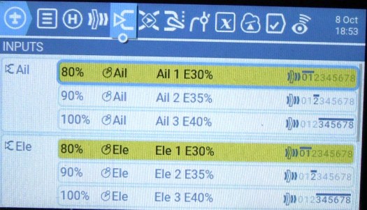
Touch on the settings box at the bottom. It has a gear symbol on it. In the Modes area, touch on each of the modes from 2 to 8 to deselect them. So, we end up with Modes 0 and 1 selected. We include Mode 0 in that we do not want to take any chance that there could be a Mode in which the aileron isn’t going to work. So, at the bottom end we include 0, and at the top end we will include 3 – 8. Press RTN several times to get back to the main Inputs menu.
Touch on the Ail line again. This time, pick “Copy.” Touch on the Ail line yet again. Select “Paste after.” Now touch the line that was just added and “Copy.” Touch on it and “Paste after.” You should now have three identical “Ail” lines.
Touch on the second Ail line and pick Edit. Alter the line name to “Ail 2.” Dial up the weight to 90%. Touch off it, scroll down to “Curves” and bring the Expo up to 35%. Now, go to the bottom and click the settings line.to the Inputs screen. Now Edit the third Ail line to have the line name “Ail 3,” a Rate of 100%, Expo of 40%, and Modes 3 to 8 highlighted.
We now get to do basically the same thing for the elevator, “Ele,” and rudder, “Rud. You don’t need to do anything with the throttle.
Check to see that all of the modes are covered in each control segment and that they look consistent.
Mixes and Outputs
The next two tabs in the Model Menu are Mixes and Outputs. You don’t need to do anything with these now, but it’s good to understand what they are. The four mixes that are already there are just simply saying, let’s just use the outputs that have been worked out in the Inputs tab. They are good enough without need of modification.
But, if, let’s say, you wanted to have the rudder moved a bit along with the aileron, we could add a line under rudder to add a small percentage of the aileron input along with what the rudder stick might be telling it to do. Something similar could be done for the elevator for changes to the flaps. In adding in the mix, you will copy a line and insert it after the one you copied. You will then be adding the input for what you are mixing in.
There also could be some things added in here that are not in the Inputs tab. Say, landing gear. They are just up or down, so a mix could be added with its input coming directly from a switch, rather than an item in the Inputs section.
Note that every channel that is going to be used must be included in the Mixes. Down the left you see the channel numbers. To add another, you just scroll to the bottom, click on the +, and select the channel number that you want to add. You will then put in what you want for the source of the input.
The next tab after Mixes is Outputs. The only thing you are going to do with that is to reverse any channels that need it.
Special Functions
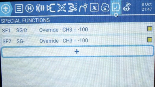
We need to add a throttle lock. The best place to do that is in Special Functions, the next to last tab in the Model Menu. Click the + to add one and select the first “SF” number. The trigger needs to be the switch that you are going to use. So, touch the box next to “Trigger” and then move the switch into the position where you want the throttle to be locked. Touch it on the screen or click the scroll wheel. Select channel 3, give it a value of -100 and then enable it. If you chose a three-position switch and you only want the throttle armed in one position, then add a second Special Function with the second position in which you want it disabled.
Final Adjustments
You now have everything functional, but obviously, you need to make specific adjustments for your model. Adjust the rates so that your control surfaces move the distances recommended in their directions. Make sure they all move in the correct direction. Secure the plane and make sure the prop is spinning in the right direction. Remember that you reverse its direction by swapping two of the power leads, or with programming, and not by reversing the Output.
Advanced Matters
While this gives you a really good basic understanding, there still is more to learn. Some of the following are covered in our YouTube videos at YouTube.com/@rcjim. The rest are most likely to be in the works!
- Flaps
- Mixing details
- Differential ailerons
- Express LRS
- Telemetry
- Sounds
- Custom graphics
Check them out under our Radiomaster YouTube playlist: CLICK HERE

Jim ,thanks for such s detailed article. I fly fixed wing and have the TX16s and NX10. I actually think the tx16 is a better made product from a quality perspective. However the Spektrum Airware is hard to get off! Hands down thd flexibility and possibilities of the TX16 beat Spektrum.The learning and retention curve however is a little too much .I can be up to speed one day and a few weeks later have to read up again for an obscure but important basic feature. I find I can pick up the NX10 6 months later and program a 7 ch setup by instinct. For my type of flying the Spektrum wins on ease of use especially at the field for a small tweak and there is nothing that tx cant do for me. But I love the TX16 for its possibilities and gadget appeal and great price. Your article and videos may get me there yet! Many thanks Alan UK
LikeLike
Hi Alan, I understand what you are saying. But now that I’m using Radiomaster several times a week, and hardly ever using Spektrum, I’m now in the opposite frame of mind. Radiomaster I find naturally intuitive. With Spektrum I have to poke around a bit while the cobwebs clear out of my head! But I think what you are saying is correct. Generally Spektrum have tried to make things as simple as possible, and Radiomaster/Edge TX is trying to add every amount of capability that’s possible.
LikeLike
Hi Jim , with all the heat that sometimes comes when discussing various radio brands I think you have managed to summarise perfectly the differences betwen the two whilst being very objective.
I guess if I was using the TX 16 regularly and using templates it would sooner or later burn a track in my weay but usable brain !
Cheers Alan
LikeLike