


This handy little test board is inexpensive and practical. I bought mine from Aliexpress. These instructions include information that they provide online along with my own observations. Note that the printed instructions provided with the unit were in Chinese, and the website that they provide a link to is quite unhelpful.
What it is good for
You may already have a battery tester that includes a servo tester. Those work great for setting up a plane, getting the controls in the correct neutral position and checking control throws. This tester does all of that plus more.
The additional things that you can do include:
- Toggle quickly between 1000, 1500 and 2000 µs
- Output can be sent to two servos at the same time
- Test 333 Hz servos between 495 and 1006 µs
- Test extended travel servos that can operate from 480 to 2526 µs
- Check the µs value for the pwm output of a receiver or controller to a servo
And it does have a brighter, very readable display.
What it doesn’t do as well is the speed of the rapid oscillation between the minimum and maximum values to check the responsiveness of a servo. It’s also not in a durable plastic case, so it isn’t suitable for throwing into your box of gear that you take to the field. If you have a 3D printer, you could remedy that! However, since it uses a servo style connector for the input and not a balance connector, it’s not really designed for checking your flight batteries.
Basic specs
- The working voltage range is 4.5V-8.4V
- Naturally it is for pwm signals
- 50 Hz output for most menu items. 333 Hz for one.
- Pwm values are +/- 1 µs for all modes except the “Robot” mode. That one is +/- 2 µs.
- Voltage values are +/- 0.22 V.
Connections
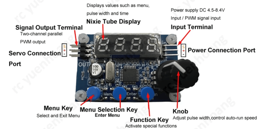
If you are using it to operate one or two servos, then you plug in your power supply on the right-hand side and the servo(s) on the left. Being able to plug in two servos means that for things like single channel ailerons or flaps you can have both sides held in a given position to allow you to make sure they are even.
If you are using it to measure the pwm pulse width for a receiver or controller output, just plug that into the right-hand side, ensuring that it also has power on the middle connector.
Note that the ground wire is closest to you on both sides.
Control operation
The left button toggles you through the menu items listed below. When you reach the one you want, press the middle button. The right-hand button is only used with the PA05 menu item.
The knob is used to either change the pwm pulse width of the output or change the rate of change of the pulse width when it is automatically cycling between minimum and maximum values.
Menu details
PA01 Manual control mode
Simply dial the pwm value that you want. It will send that value to the servo to move it into position. The range is 990 to 2013 µs.
PA02 Automatic control mode
The control board will automatically cycle back and forth between minimum and maximum pulse widths. The dial will change how fast it is trying to do that. If the servo isn’t reaching the normal maximum and minimum positions, then that’s an indication that it isn’t quick enough to respond to such a rapid change.
PA03 Manual test servo mode
The servo will quickly move to the 1000 µs position, then do one quick, full cycle between the extremes, one slow cycle between the extremes, and finally move quickly to the 1500 µs position.
The dial will alter the speed of the quick movements.
PA04 Automatic test servo mode
Same as PA03 only instead of finishing with the quick move to 1500 µs, it simply continues to repeat the previous movements.
PA05 Three signal point test mode
The middle button will toggle between 1000 and 2000 µs. The right-hand button will toggle between 1000, 1500, 2000 and back.
PA06 Gyro servo manual mode
This is for servos that operate on 333 Hz. The pwm range is reduced to 495 to 1006 µs. The dial selects the pwm pulse width desired.
PA07 Robot servo manual mode
The pwm range is extended in this mode: 480 to 2526 µs. This provides a greater range of movement when using a radio that supply that full pulse range.
PA08 Signal detection mode
In this mode the digital readout is the pwm pulse width of the incoming signal.
PA09 Voltage test mode
The voltage applied at the input is displayed.
See the video:
